Introduction: From Simple Logic to Smart Robotics
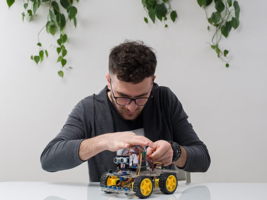
Ever imagined building your own robot that can follow a line automatically—just like autonomous delivery bots or warehouse sorters?
In this DIY robotics project, we’ll create a Line Follower Robot using Python and Arduino UNO, designed especially for beginners in robotics and AI automation.
This guide bridges the gap between coding and electronics, combining Python for logic and serial communication with Arduino for sensor control. By the end, you’ll understand how sensors, motors, and algorithms work together to make a robot think and move intelligently.
Whether you’re a student, hobbyist, or aspiring robotics engineer, this step-by-step tutorial will give you hands-on experience with AI-powered robotics using Python and Arduino.
- Introduction: From Simple Logic to Smart Robotics
- Components Required for Line Follower Robot
- How Line Follower Robot Works
- 🧩 Circuit Connection Diagram (Explanation)
- Step 1: Arduino UNO Code for Line Follower Robot
- 💻 Step 2: Python Code for Monitoring and Control
- 🧭 Step 3: Understanding the Logic
- 🌐 Step 4: Adding AI Enhancement (Optional Upgrade)
- 🔋 Step 5: Powering, Testing, and Troubleshooting
- 🧠 Learning Outcome:
- 🏁 Conclusion
Components Required for Line Follower Robot
Here’s what you’ll need to get started (readily available online or in electronics stores):
| Component | Quantity | Description |
| Arduino UNO | 1 | The brain controlling motor actions |
| L293D Motor Driver Module | 1 | Controls direction and speed of DC motors |
| IR Sensor Module | 2 or 3 | Detects black and white surface lines |
| DC Motors with Wheels | 2 | Drive mechanism for movement |
| Chassis Board | 1 | Body of the robot |
| Jumper Wires | As required | Connections between modules |
| Battery (9V or 12V) | 1 | Power source |
| USB Cable | 1 | To connect Arduino with laptop |
| Python (on PC) | 1 | For programming logic and serial communication |
How Line Follower Robot Works
The line follower robot operates using a simple principle — light reflection.
- A black line absorbs infrared (IR) light, while a white surface reflects it.
- IR sensors detect the reflection, sending signals to the Arduino UNO, which then decides whether the robot should move forward, turn left, or turn right.
- The Arduino communicates with Python, where the control logic and data visualization can happen simultaneously.
Think of it as a small-scale AI navigation system where the robot “sees” and “thinks” before moving — the foundation of machine learning in robotics.
🧩 Circuit Connection Diagram (Explanation)
If you’re building this on a breadboard or soldered setup, here’s how to wire it:
- Connect IR sensor OUT pins → Arduino digital pins (2, 3)
- Connect Motor Driver IN pins → Arduino pins (8, 9, 10, 11)
- Connect Motor Driver OUT pins → DC motors
- Connect Motor Driver VCC → Battery +
- Connect GND of all components together (common ground)
Step 1: Arduino UNO Code for Line Follower Robot
Below is the Arduino C++ code that controls motor movements based on sensor inputs.
// Arduino Line Follower Robot Code
int leftSensor = 2;
int rightSensor = 3;
int motorLeft1 = 8;
int motorLeft2 = 9;
int motorRight1 = 10;
int motorRight2 = 11;
void setup() {
pinMode(leftSensor, INPUT);
pinMode(rightSensor, INPUT);
pinMode(motorLeft1, OUTPUT);
pinMode(motorLeft2, OUTPUT);
pinMode(motorRight1, OUTPUT);
pinMode(motorRight2, OUTPUT);
Serial.begin(9600);
}
void loop() {
int leftValue = digitalRead(leftSensor);
int rightValue = digitalRead(rightSensor);
// Both sensors detect white → go forward
if (leftValue == 1 && rightValue == 1) {
moveForward();
Serial.println(“Moving Forward”);
}
// Left detects black → turn right
else if (leftValue == 0 && rightValue == 1) {
turnRight();
Serial.println(“Turning Right”);
}
// Right detects black → turn left
else if (leftValue == 1 && rightValue == 0) {
turnLeft();
Serial.println(“Turning Left”);
}
// Both detect black → stop
else {
stopRobot();
Serial.println(“Stop”);
}
}
void moveForward() {
digitalWrite(motorLeft1, HIGH);
digitalWrite(motorLeft2, LOW);
digitalWrite(motorRight1, HIGH);
digitalWrite(motorRight2, LOW);
}
void turnLeft() {
digitalWrite(motorLeft1, LOW);
digitalWrite(motorLeft2, LOW);
digitalWrite(motorRight1, HIGH);
digitalWrite(motorRight2, LOW);
}
void turnRight() {
digitalWrite(motorLeft1, HIGH);
digitalWrite(motorLeft2, LOW);
digitalWrite(motorRight1, LOW);
digitalWrite(motorRight2, LOW);
}
void stopRobot() {
digitalWrite(motorLeft1, LOW);
digitalWrite(motorLeft2, LOW);
digitalWrite(motorRight1, LOW);
digitalWrite(motorRight2, LOW);
}
💻 Step 2: Python Code for Monitoring and Control
We’ll now write a Python script to read data from the Arduino through Serial Communication and visualize robot activity.
import serial
import time
# Establish connection with Arduino
arduino = serial.Serial(‘COM3’, 9600)
time.sleep(2)
print(“Connected to Arduino”)
while True:
if arduino.in_waiting > 0:
data = arduino.readline().decode(‘utf-8’).strip()
print(f”Robot Status: {data}”)
✅ This Python code:
- Reads serial data sent from Arduino (Moving Forward, Turning Left, etc.)
- Helps you monitor the robot’s movement in real-time
- Can later be expanded to add AI-based decision-making, like obstacle avoidance or adaptive learning.
🧭 Step 3: Understanding the Logic
Let’s break down the intelligence behind this robot:
- Sensor Input: IR sensors continuously check the surface.
- Decision Layer (Arduino): Based on sensor readings, logic decides movement.
- Action Layer (Motors): Motor driver executes turn/stop/forward commands.
- Feedback Loop (Python): Data is displayed, logged, or used for advanced AI logic.
This structure mimics how autonomous systems like self-driving cars operate — using sensors → control logic → feedback → optimization.
🌐 Step 4: Adding AI Enhancement (Optional Upgrade)
You can extend this project by integrating AI and Machine Learning:
- Computer Vision — Attach a camera and use Python’s OpenCV to detect colored lines instead of IR sensors.
- Reinforcement Learning — Let the robot learn by trial and error which turns lead to better path following.
- Data Logging — Save sensor data to CSV files for training models later using TensorFlow or Scikit-learn.
This way, your simple line follower can evolve into a smart AI robot capable of navigating dynamically changing paths. Keep following blog for this upgrades and codes for DIY and learn.
🔋 Step 5: Powering, Testing, and Troubleshooting
✅ Testing Steps:
- Place the robot on a black line over a white surface.
- Power it using a 9V battery or USB.
- Observe movement — adjust sensor position or motor direction if it doesn’t follow properly.
⚠️ Common Fixes:
- Robot moves opposite? Swap motor wires.
- Always turning? Adjust sensor sensitivity using IR sensor potentiometers.
- No movement? Check power connections and ground continuity.
🧠 Learning Outcome:
By building this Line Follower Robot with Python and Arduino, you learn:
- How sensors interact with microcontrollers.
- How to write control logic in C++ (Arduino) and monitor it in Python.
- Fundamentals of robotic navigation, automation, and AI-based behavior.
This single project lays the groundwork for more complex systems like:
- Obstacle Avoiding Robots
- Maze Solvers
- Delivery Bots
- Autonomous AGVs (Automated Guided Vehicles)
🏁 Conclusion
This DIY robotics project proves how Python and Arduino together can transform a simple setup into an intelligent machine. You’ve just built the foundation of AI-driven robotics, where every line of code teaches your robot how to see, decide, and act.
Stay tuned for our next robotics blog — where we’ll explore AI-powered Object Detection Robots using TensorFlow Lite and Arduino Edge Impulse!