Introduction: Building Intelligent Robots with DIY Learning
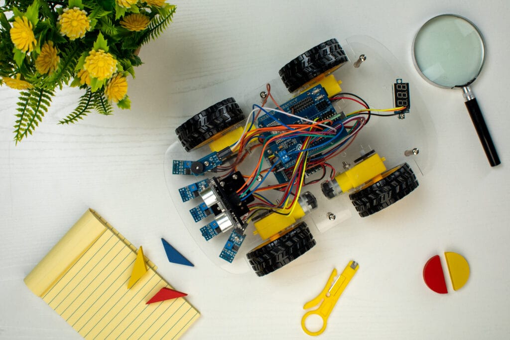
Robotics in 2025 has evolved from basic motor experiments to smart, sensor-driven automation. One of the most exciting projects for DIY learners is building an advanced line follower robot using Arduino and Python. This project combines robotics fundamentals, embedded systems, and artificial intelligence concepts to train both beginners and intermediate developers in real-world automation systems.
In this complete DIY robotics guide, you’ll learn how to design, assemble, and program a smart line follower robot using IR sensors, servo motors, Arduino UNO, and Python-based control and data visualization. We’ll cover every step, from wiring and calibration to adding intelligent behavior with sensor fusion.
What Is a Line Follower Robot?
A line follower robot is an autonomous robot that detects and follows a line or path (usually black tape on a white surface). It uses infrared (IR) sensors to sense changes in light reflection, sending signals to Arduino, which controls the motors to navigate the track.
Unlike basic models, an advanced line follower robot uses multiple sensors and algorithms (like PID control and sensor fusion) to ensure speed, accuracy, and stability. With integration of Python, data visualization and decision-making become smarter than ever.
- Introduction: Building Intelligent Robots with DIY Learning
- What Is a Line Follower Robot?
- Components Required for the Advanced DIY Line Follower Robot
- Hardware Components
- Software and Tools
- Understanding How the Robot Works
- Circuit Connection Diagram (Conceptual Overview)
- DIY Arduino Code for Line Follower Robot (With PID Control)
- Advanced Step: Integrating Python for Live Monitoring
- Sample Python Code for Data Logging
- Step-by-Step DIY Assembly Instructions
- Optimization Tips for a Smarter Line Follower Robot
- Common Troubleshooting DIY Steps
- Real-World Application of Line Follower Robots
- Conclusion: Innovation Through DIY Robotics
Components Required for the Advanced DIY Line Follower Robot
Here’s what you need to build your robot:
Hardware Components
- Arduino UNO (Microcontroller)
- L298N Motor Driver Module
- 2 DC Geared Motors with wheels
- IR Sensor Array (5-channel preferred)
- Li-ion Battery (7.4V-12V)
- Chassis (Car Frame)
- Jumper Wires and Breadboard
- Switch, Screws, and Mounting Accessories
Software and Tools
- Arduino IDE – to write the code logics and upload the code into the arduino board.
- Python 3.x – for control, logging, and live visualizations.
- Jupyter Notebook or VS Code – for Python execution.
Understanding How the Robot Works
The mechanism follows a simple principle:
- IR sensors detect the reflected light intensity off the surface.
- When the sensor detects black, it sends LOW signal; when detecting white, it sends HIGH signal.
- The robot’s control program adjusts motor speeds accordingly to stay on track.
In advanced setups, the robot uses a PID control algorithm that continuously corrects its position, enabling faster and smoother turns.
Circuit Connection Diagram (Conceptual Overview)
- Connect IR Sensors to Arduino’s analog/digital pins (A0–A4 for 5-sensor array).
- L298N Motor Driver
- IN1, IN2 → Right motor control pins.
- IN3, IN4 → Left motor control pins.
- 12V and 5V power pins to battery and Arduino VIN.
- Motors to output pins of L298N.
- Ground (GND) all modules together.
DIY Arduino Code for Line Follower Robot (With PID Control)
Arcuino code with C++ programmig
#define LEFT_SENSOR A0
#define MIDDLE_SENSOR A1
#define RIGHT_SENSOR A2
#define ENA 10
#define ENB 11
#define IN1 9
#define IN2 8
#define IN3 7
#define IN4 6
float Kp = 18;
float Ki = 0;
float Kd = 5;
float error = 0, P, I, D, previousError = 0, PIDvalue;
int baseSpeed = 100;
void setup() {
pinMode(LEFT_SENSOR, INPUT);
pinMode(MIDDLE_SENSOR, INPUT);
pinMode(RIGHT_SENSOR, INPUT);
pinMode(IN1, OUTPUT);
pinMode(IN2, OUTPUT);
pinMode(IN3, OUTPUT);
pinMode(IN4, OUTPUT);
analogWrite(ENA, baseSpeed);
analogWrite(ENB, baseSpeed);
}
void loop() {
int left = digitalRead(LEFT_SENSOR);
int mid = digitalRead(MIDDLE_SENSOR);
int right = digitalRead(RIGHT_SENSOR);
if(mid == HIGH) error = 0;
else if(left == HIGH) error = -1;
else if(right == HIGH) error = 1;
P = error;
I = I + error;
D = error – previousError;
PIDvalue = (Kp * P) + (Ki * I) + (Kd * D);
previousError = error;
int leftSpeed = baseSpeed – PIDvalue;
int rightSpeed = baseSpeed + PIDvalue;
moveMotors(leftSpeed, rightSpeed);
delay(10);
}
void moveMotors(int leftSpeed, int rightSpeed) {
leftSpeed = constrain(leftSpeed, 0, 255);
rightSpeed = constrain(rightSpeed, 0, 255);
analogWrite(ENA, leftSpeed);
analogWrite(ENB, rightSpeed);
digitalWrite(IN1, HIGH);
digitalWrite(IN2, LOW);
digitalWrite(IN3, HIGH);
digitalWrite(IN4, LOW);
}
This program uses PID logic for smooth tracking and minimal deviation at turns, ensuring faster performance and stable movement.
Advanced Step: Integrating Python for Live Monitoring
With Python, you can monitor the robot’s path, sensor readings, and errors via serial communication.
Sample Python Code for Data Logging
Code written in python
import serial
import matplotlib.pyplot as plt
ser = serial.Serial(‘COM5’, 9600)
errors = []
def fetch_data():
while True:
data = ser.readline().decode(‘utf-8’).strip()
if data:
try:
error_val = float(data)
errors.append(error_val)
plt.clf()
plt.title(‘Line Following Error (PID)’)
plt.xlabel(‘Iteration’)
plt.ylabel(‘Error Value’)
plt.plot(errors[-100:], color=’blue’)
plt.pause(0.05)
except ValueError:
pass
fetch_data()
This script continuously reads sensor error data from Arduino via serial output and visualizes the robot’s performance in real-time.
Step-by-Step DIY Assembly Instructions
- Assemble the Chassis: Mount the motors and wheels.
- Attach IR Sensor Array: Precisely align it at the base facing downward.
- Connect Arduino and Motor Driver: Follow the circuit described earlier.
- Upload Code via Arduino IDE: Check motor rotation and logic direction.
- Calibrate Sensors: Adjust IR sensitivity using onboard potentiometers.
- Test and Tweak: Run on a track with gentle curves and then increase complexity.
Optimization Tips for a Smarter Line Follower Robot
- Use more IR sensors (5 or 7) for smoother direction adjustments.
- Add Ultrasonic and Color Sensors for obstacle and color detection.
- Upgrade Logic: Try neural network control instead of PID.
- Use Python Dashboards for performance tracking.
- Include Bluetooth or Wi-Fi modules for IoT integration.
Common Troubleshooting DIY Steps
| Problem | Possible Cause | Fix |
| Robot doesn’t move | Wrong motor wiring | Swap motor terminals |
| Only moves in one direction | Bad IR signal or sensor misalignment | Reposition sensor array |
| Wobbly movement | Poor line contrast | Use thick black tape |
| Overreacts on turns | PID gains too high | Lower Kp or Kd values |
Real-World Application of Line Follower Robots
- Automated Guided Vehicles (AGVs) used in manufacturing lines.
- Package Delivery Bots navigating warehouse routes.
- Smart Mobility Solutions in logistics and education labs.
By understanding this basic yet powerful model, DIY learners gain the foundation for building self-driving robots and intelligent robotic systems.
Conclusion: Innovation Through DIY Robotics
By blending Arduino hardware control and Python analytics, this DIY advanced line follower robot project provides a practical pathway for learning robotics, AI, and automation. Each DIY modification—whether adding sensors, improving algorithms, or visualizing data—advances your knowledge toward building autonomous, intelligent systems.
This project is ideal for continuous learners who want to bridge the gap between mechanical hardware and intelligent algorithmic control.